Using Parallel Fiber Cabling for Network Upgrades
It’s no secret that enterprise and consumer demands are impacting data centers and networks. As speed requirements go up, layer 0 (the physical media for data transmission) becomes increasingly critical to ensure link quality.
Many organizations are looking for an economical, futureproof migration path toward 100G (and beyond). Multimode fiber (MMF) cabling systems continue to be the most popular, futureproof cabling and connectivity solution.
Both duplex and parallel cabling are options for network upgrades. A few weeks ago, we discussed duplex MMF cabling. In this, we’ll discuss parallel MMF cabling.
Parallel Fiber Cabling
When transceiver technology can’t keep up with Ethernet speed requirements, the most obvious solution is to move from duplex to parallel fiber cabling.
Although using BiDi (bi-directional) and SWDM (shortwave wavelength division multiplexing) transceivers can reduce direct point-to-point cabling costs, they do not support breakout configuration (e.g. 40G switch ports to four 10G server ports), which is a very common use in data centers.
According to research firm LightCounting, approximately 50% of 40GBASE-SR4 QSFP+ form factors are deployed for breakout configuration; the other 50% are deployed for direct switch-to-switch links.
As a matter of fact, 40G QSFP+ and 100G QSFP28 are the most popular form factors used for Ethernet switches in data centers. QSFP (quad small form-factor) is a bi-directional, hot-pluggable module mainly designed for datacom applications. QSFP+/QSFP28 has a 2.5x data density compared to SFP+/SFP28, using four parallel electrical lanes. The optical interface is a receptacle for MPO female connectors. Four fibers (1, 2, 3 and 4) transmit the signal; the other four fibers (9, 10, 11 and 12) receive the optical signal.
QSFP transceivers, paired with parallel fiber connectivity with a one-row MPO-12 (Base-8 or Base-12) interface, can support flexible breakout or direct connection.
- 40G/100G direct links are typically used in switch-to-switch links, which can be supported by duplex or parallel fiber cabling.
- 40G/100G Ethernet ports can be configured as 4x 10G or 4x 25G ports to support 10G/25G server uplinks.
- 40G/100GBASE-SR4 transceivers only use eight fiber threads in an MPO-12 connector; therefore, Base-8 is a cost-optimized cabling solution that allows 100% fiber utilization.
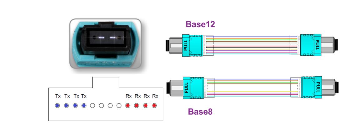
MPO-12 (Base-8 and Base-12)
When migrating from 10G cabling infrastructure to a parallel fiber cabling infrastructure, MPO permanent links can be reused for connectivity optimization in one of two ways:
- Option No. 1: When used for 40G or 100G switch-to-switch direct links, an MPO-12 (Base-8) to MPO-12 (Base-12) conversion can allow 100% fiber reutilization of the installed horizontal cabling. In this example above, 3x MPO-12 (Base-8) patch cables are converted into two MPO-12 (Base-12) trunk cables.
- Option No. 2: When connecting to 10G or 25G server ports, MPO-12 to LC Duplex hydra cable assemblies support breakout configuration from 40G or 100G switch ports, with the main interconnect MPO fiber trunk cable via fiber patch panel.
Moving beyond 100G, new form factors such as QSFP-DD, OSFP and CFP8 have also been adopted by IEEE 802.3 Ethernet task groups to support new transceiver PMD (physical medium dependent) sublayers, such as 200GBASE-SR8 and 400GBASE-SR16.
A few new array connector types, such as MPO-16, MPO-24 and MPO-32, have also been added to the IEEE 802.3 standard and ANSI/TIA structured cabling standards.
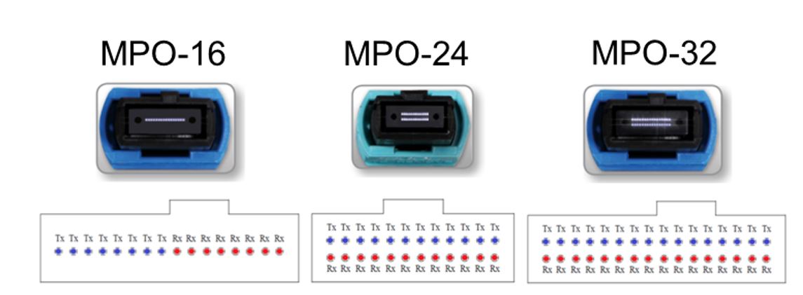
New parallel fiber connectors
Designed to support higher-density parallel fiber connectivity, these new connectors are not readily compatible with the most popular installed-base MPO-12 connectivity (connector and trunk cable). Additional adaptors will be needed, and critical connector performance (e.g. insertion loss, return loss, mating force and reliability) will take time to improve.
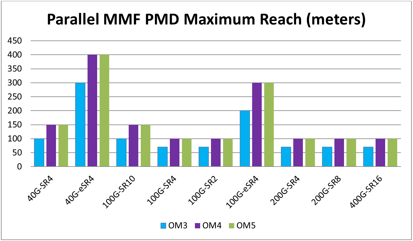
Parallel MMF PMD maximum reach
Above, parallel multimode PMD transceiver choices from 40G to 400G are showcased. In many cases, installed brownfield parallel fiber cabling can satisfy your speed-upgrade needs, but here are a few tips for the next upgrade cycle:
- As only one wavelength, 850 nm is used in these new transceivers; OM5 doesn’t have a clear advantage over OM4 in supporting longer reach.
- The maximum reach will decrease at higher bit rates (with 25G and 50G per wavelength), with a maximum reach of 70 m in OM3 and 100 m in OM4 and OM5.
- To satisfy longer reach links in data centers, some vendors have already released extended-reach multimode transceivers, such as 100G-eSR4, to support a reach of up to 200 m in OM3, and 300 m in OM4 and OM5.
- The current 400GBASE-SR16 IEEE standard for 400G transceivers will need a new MPO-32 interface. There has not been great interest in this product due to the high cabling and connectivity system costs, and the lack of backward compatibility with MPO-12 and MPO-24.
- The IEEE 802.3 Next-Generation MMF PMDs group is currently working on reducing fiber counts and leveraging newly developed SWDM technology.
- Using four wavelengths (850 nm, 880 nm, 910 nm and 940 nm) and transmitting 25G over each wavelength can reduce the 400G PMD fiber counts from 32 to eight, making it backward compatible with MPO-12 MMF cabling.
- Using eight wavelengths and transmitting 50G (PAM4) over each wavelength can reduce 400G PMD fiber counts from 32 to two, which will also make it backward compatible with LC Duplex MMF cabling.
- Using four wavelengths (850 nm, 880 nm, 910 nm and 940 nm) and transmitting 25G over each wavelength can reduce the 400G PMD fiber counts from 32 to eight, making it backward compatible with MPO-12 MMF cabling.
To meet anticipated needs in the future, many organizations are looking for an economical, futureproof migration path toward 100G (and beyond). As these speeds go up, layer 0 (the physical media for data transmission) becomes increasingly critical to ensure link quality.
Make sure you subscribe to our blog updates to learn about the latest in network upgrades. Learn more about our network upgrade capabilities here.
About the Author
![System.String[]](https://assets.belden.com/transform/d88d257f-c23d-4a61-b354-d49d9932ec65/qing-xu?io=transform:fill,width:300,height:300)
With 13 years of experience in optical communications and photonics device design, Qing Xu is a subject-matter expert in not only optical fiber technology, but also signal transmission, data center trends, fiber/copper connectivity and structured cabling. During his time with Belden, he closely monitored and participated in industry activities related to optical fiber communications systems, data center technology and trends.