Maintaining Polarity—A Not-So-Simple Necessity
In today's Data Centers, 12-fiber preterminated array cabling is frequently used to establish an optical path between switch tiers. Accomplishing this path in a way that matches the transmit signal (Tx) on one switch port to the corresponding receive signal (Rx) on the other switch port is referred to as polarity.
 In August 2012, TIA published Addendum 2 to the ANSI/TIA 568-C.0 Generic Telecommunications Cabling for Customer Premises Standard that provides three example methods to establish polarity of optical fiber array systems—Connectivity Method A, B and C. While the standard makes no preference for one method over another, it does recommend that a method be selected in advance and maintained throughout an installation; otherwise it won't work. The TIA standard addresses both multiple duplex signals (for 10 Gigabit Ethernet or 8, 10 and 16 Gigabit Fibre Channel) and parallel signals (for 40 Gigabit Ethernet). The current migration to 40 Gigabit Ethernet warrants taking a closer look at polarity methods for both applications.
Multiple Duplex Signals
The systems components deployed for multiple duplex signals includes a breakout cassette at each end that consists of a multi-fiber push-on (MPO) adapter to multiple duplex adapters, typically LC. Preterminated 12-fiber trunk cables (or multiples thereof) connect to the MPO adapter on the back of the two cassettes, and duplex patch cords are used to connect the equipment to the front of the cassettes.
The TIA standard defines two types of duplex fiber patch cords—A-to-B and A-to-A. It also defines two types of MPO adapters used in the cassettes—Type A and Type B. The difference between the MPO adapter types is the orientation of the internal MPO connector with respect to how it mates with the array cable. The trunk cables are defined as either Type A, Type B or Type C. Type C trunk cables feature a special cross-over configuration that essentially flips each pair so that fiber 1 and 2 connect to 2 and 1, and so on. The components used in Connectivity A, B and C polarity methods are color coded in Figure 1 to distinguish between the different designations as follows:
- A-to-B duplex patch cord (KeyUp-to-KeyUp)
- A-to-A duplex patch cord (KeyUp-to-KeyUp)
- Type A MPO adapter (KeyUP-to-KeyDown)
- Type B MPO adapter (KeyUp-to-KeyUp)
- Type A trunk cable (KeyUp-to-KeyDown)
- Type B trunk cable (KeyUp-to-KeyUp)
- Type C trunk cable (KeyUp-to-KeyDown)
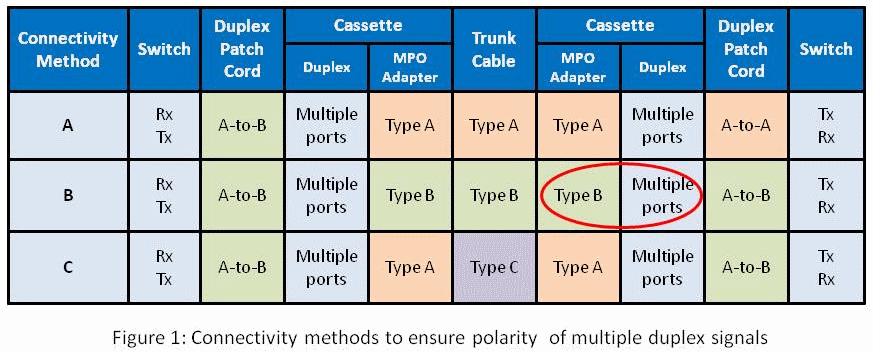
A simple way to look at these polarity methods is that Method A is the most straight forward but requires a different patch cord at one end. Method B uses the same patch cord at both ends, but the cassettes (circled in red in Figure 1) must be flipped over at one end so that the fiber that originated in position 1 is mapped to position 12. Method C is a variant of Method A, but with the cross-over implemented in the trunk cable instead of the patch cord. Both Method B and Method C have the advantage of using the same patch cords at both ends.
Parallel Signals
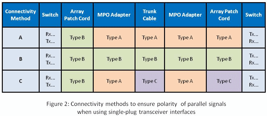
Figure 2 illustrates corresponding Connectivity Methods A, B and C to establish polarity for parallel signals using an MPO transceiver interface with one row of fibers. For these parallel array systems, the breakout cassettes are replaced with MPO-to-MPO pass-through adapters and the duplex fiber patch cords are replaced with 12-fiber patch cords. Note that when using Method C for parallel signals, a Type C cross-over patch cord is required at one end.
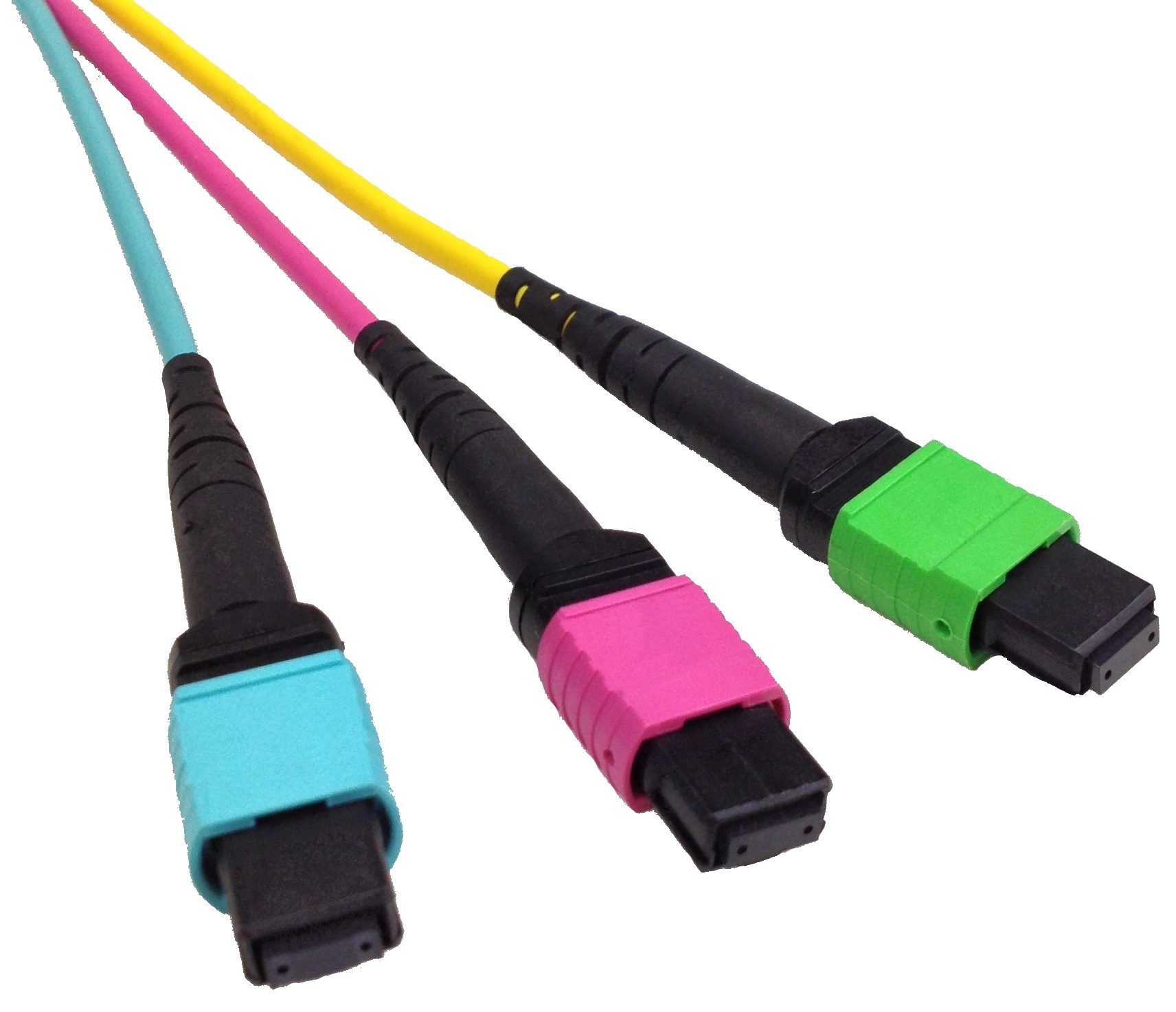
An important point to remember is that MPO plugs use alignment pins. MPO transceivers typically have pins (Male) and the patch cords from transceiver to patch panel are typically unpinned (Female) on both ends. The array cables are typically pinned (Male) on both ends.
With multiple methods to ensure polarity, there are multiple ways to get it wrong. Obviously, maintaining polarity is not as simple as it seems. For more information consult the ANSI/TIA-568-C.0-2 Addendum.
About the Author
![System.String[]](https://assets.belden.com/transform/1290e91f-b9b1-45bb-b59c-1bed98597986/paul-kish?io=transform:fill,width:300,height:300)
Looking back at his 42-year career in the cabling industry, Paul Kish was one of the founding fathers of the industry. Retiring from Belden in 2015, Paul was recognized as an expert in cable transmission. He served as a role model, an innovator and a thought leader. Paul was a key contributor to the development of cabling standards with TIA, ISO and IEEE, and also served on the BICSI Technical Information & Methods Committee.