Reusing Single-mode Fiber? Here’s What the G.652D and G.657A1 Standards Have to Say
Historically – especially in the telecom world, where the fiber cable deployment is very costly – operators expected active equipment and line card upgrades to allow more data to be transported over the same installed fiber threads. This allowed them to maximize their return on investment by delaying a fiber cable upgrade.
This is also true in data center environments where thousands (or millions) of fiber threads are installed to connect server clusters and switches. Data center managers may expect to reuse the installed permanent fiber cable trunk as long as possible to delay the financial impact of a capital investment in new infrastructure.
When it comes to system upgrades, it’s essential to make wise decisions that will provide long-term sustainability and system scalability for your data center; installing new optical fiber requires a huge investment with a return that may not be fully realized for several years.
This blog is the second in a series of three where we walk you through the risks of reusing installed fiber cable, and help you understand how fiber cable infrastructure performance and quality could impact business operations. You can read the first blog in the series here. In the first blog, we explained the risks associated with fiber installation and routing with traditional fiber cable, and introduced new industry-standard, bend-insensitive fibers.
In this week’s blog, we will elaborate on singlemode fiber (SMF) standard specifications, and help you decide whether your current premises fiber infrastructure can be kept or should be replaced.
<br="">
SMF Applications and Specifications
SMF standards for long-distance optical communications – ITU-T – were developed by the International Telecommunication Union. Cable characteristics of NDSF (non-dispersion-shifted fiber), which is the oldest (and still most widely deployed) SMF, are specified in ITU-T G.652; bend-insensitive SMF and cable characteristics are specified in ITU-T G.657.
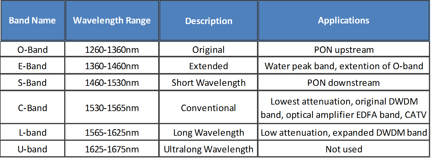
SMF band wavelength range
SMF was originally optimized for use in the 1310nm wavelength region in premises cabling, but it can also be used in the 1550nm wavelength region. The zero dispersion wavelength range is set between 1300nm to 1324nm to minimize transmission penalty.
This fiber cable was installed mostly in the 1980s, but there was a high absorption wavelength range due to -OH (hydroxyl) molecules within the fiber, which makes the E-band (water peak band) unusable. (The E-band represents the region in which a standard fiber is most affected by attenuation caused by the hydroxyl molecules in the glass core structure.)
In metro and access networks, one fiber carries signals on multiple wavelengths and over multiple wavelength bands to increase overall bandwidth and maximize fiber use. Recently, optical fiber manufacturers dramatically reduced E-band losses and made it an extension of the O-band (1310nm or below).
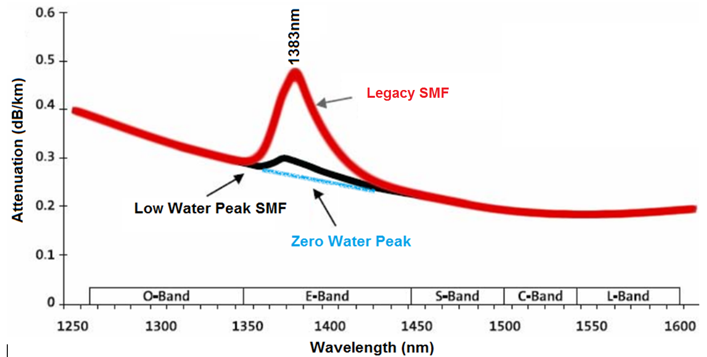
Legacy standard SMF vs. low-water-peak SMF
Note: When using E-band as an O-band extension, the transmission reach limit is set by the wavelength with the highest attenuation (i.e. lowest wavelength used in O-band). Some vendors claim that a no-water-peak fiber can essentially extend reach, but such an unpractical system would exclude the use of O-band, which is one of the most commonly used wavelengths.
The offers of “very low-water-peak fiber” also have no practical benefits, considering that the low-water-peak attenuation at 1383nm is already defined lower than that at 1310nm. The industry has therefore agreed not to pursue “no-water-peak” perfection for cost and environmental considerations (depletion of energy and drying chlorine gas).
Below, we show the ITU-T-specified SMF characteristics in G.652A and G.652B (conventional) and G.652 C and G.652D (low-water-peak).
The newer G.652C and G.652D standards have been developed to specifically reduce the water peak at the 1383nm wavelength range, and to add an additional operating E-band window for applications such as next-generation access networks and mobile fronthaul (connection between a network of centralized baseband controllers and remote standalone radio heads at cell sites). These fiber types offer extremely low attenuation around the -OH peaks and can support operation from O-band to L-band (1260nm to 1625nm).
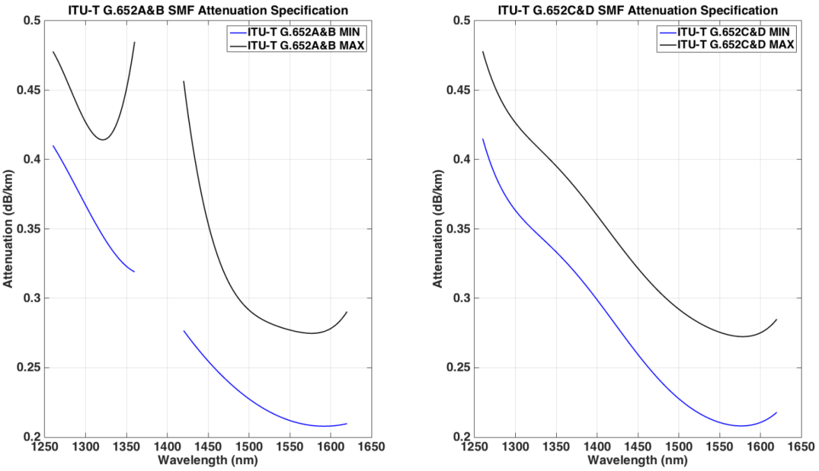
ITU-T G.652 SMF attenuation coefficients
G.652D is historically referred as non-bend-insensitive NDSF SMF standard for premises cabling:
- Compared to G.652C, G.652D offers superior polarization modal dispersion (PMD) performance:
PMD ≤ 0.2 ps/√km in G.652D vs PMD ≤ 0.5 ps/√km in G.652C. - Although G.652C and G.652D both offer excellent capabilities for shorter, unamplified metro networks and access networks, they do not fully address the needs of long-distance 1550nm transmission; chromatic dispersion (CD = ~17ps/nm∙km) is relatively high and needs dispersion compensation components.
- SMF with dispersion characteristics optimized for metro networks (long-distance transport transmission) for 1550nm are specified in G.655 and G.656. SMF characteristics optimized for ultra-long reach and submarine applications are specified in G.654.
G.657A1 is the NEW de facto standard for bend-insensitive NDSF SMF for premises cabling, thanks to optimized performance and cost balance:
- Bend-insensitive NDSF is defined in ITU-T G.657, with different minimum bending radii characteristics: G.657A1 (10 µm), G.657A2 (7.5 µm), G.657B2 (7.5 µm), G.657B3 (5 µm).
- Minimum bending radii can be optimized, but this sacrifices fiber attenuation and cost. ITU-T G.657A1 and A2 are fully compliant with G.652D, and can offer enhanced, low-loss fiber; ITU-T G.657B2 and A3 are fully compatible with G.652D (with small differences in chromatic dispersion and PMD).
- Leading optical fiber manufacturers now have SMF that is compliant with G.652D and G.657A1 standards.
Premises SMF Cable Reach and Loss Limits
Premises cabling characteristics are specified in ANSI/TIA-568.3-D and ISO-IEC 11801.
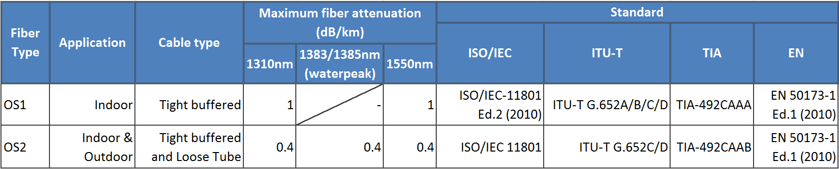
OS1 and OS2 SMF cable specifications (Click image for larger version)
By definition, OS1 is for indoor use, such as on campuses, in data centers, etc. The cable is tight buffered (manufactured into a solid medium).
OS2 is for outdoor or loose-tube use (street, underground/burial, etc.). Note: “loose tube” = not held in medium but blown or otherwise inserted into a carrier.
Because OS1 SMF cable is a two-window fiber cable (1310nm and 1550nm), most current applications adopt the OS2 cable specification with ITU-T G.652D and G.657A1 specifications.
OS2 specifications have been referred to as the de facto standard for indoor and outdoor SMF cable; OS1 has already been “grandfathered in” by ANSI/TIA-568.3-D and is not recommended for new installations.
Reusing Legacy SMF Cable
Now let’s look at the potential risks of reusing legacy OS1 for new applications:
- OS1 cannot support operation at 1383nm wavelength; therefore, it has limited bandwidth capacity.
In comparison, OS2 can support all wavelength bands from 1260nm to 1625nm. - Compared to OS2 (<0.4 dB/km), OS1 cable has a much higher attenuation coefficient (<1.0 dB/km).
This can considerably limit your link distance, especially in new, high-speed data transmission applications.
When weighing your options between on-premises and access network fiber replacement or new installation, we highly recommend replacing legacy OS1 with a new bend-insensitive OS2 (ITU-T G.657A1) SMF cabling system to support longer reach with enhanced link performance.
For other ultra-long-distance transmissions that employ exclusively C-band and L-band with optical amplifiers, refer to the ITU-T recommendations for the most appropriate SMF types.
Belden offers a variety of SMF fiber products that support longer reach with enhanced link performance. Our fiber connectivity solutions reduce complexity, increase flexibility and streamline installation. Learn more here.
</br="">About the Author
![System.String[]](https://assets.belden.com/transform/d88d257f-c23d-4a61-b354-d49d9932ec65/qing-xu?io=transform:fill,width:300,height:300)
With 13 years of experience in optical communications and photonics device design, Qing Xu is a subject-matter expert in not only optical fiber technology, but also signal transmission, data center trends, fiber/copper connectivity and structured cabling. During his time with Belden, he closely monitored and participated in industry activities related to optical fiber communications systems, data center technology and trends.