MMF Cable Loss Measurement Tests: Light Sources & Launch Conditions
The evolution and improvement of active and passive optical components (and optical fiber itself) have resulted in updated industry standards that require modifications to test measurement practices for factory qualification and field verification.
The types of light sources and methods used to measure test source launch conditions have also evolved along with the optical fiber communications systems themselves.
It’s important to emphasize that cable loss measurement of a given assembly during a factory test won’t necessarily be the same as loss measurement of that same cable assembly in field use. This is true for many reasons:
- During field verification, the actual cable loss measurement of an assembly depends on the properties of all mating components, orientation of the components and launch conditions.
- In a factory test, only the components that are part of the cable assembly are tested.
Light Sources and Modal Distribution
In the latest ANSI/TIA-568.3-D standard, OM1 and OM2 multimode fiber (MMF) are no longer recommended for greenfield installations because of their limited bandwidth. Only laser-optimized OM3, OM4 and OM5 MMF can support longer reach thanks to their lower fiber cable attenuation and enhanced bandwidth performance.
As MMF manufacturing technology improves to support higher bandwidths, light sources have also improved to support faster modulation speeds:
- LEDs were used in first-generation MMF data transmission (up to 622 Mbps); however, they can’t be turned on/off fast enough to support high-bandwidth applications.
- VCSELs are currently the most popular light source for high-speed data transmission in MMF; they are capable of modulation speeds of over 25 Gbps and are used in many high-speed networks (LANs, data centers, etc.).
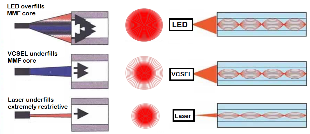
Light sources for MMF can have very different modal distribution profiles:
- LEDs spread different modes and overfill the MMF core.
- VCSELs transmit optical signals in a donut shape because most of their power concentrates in the center of the fiber.
- Lasers have the most concentrated mode of power distribution.
In MMF, the higher-order modes travel farther in the glass and are more likely scattered or absorbed (caused by fiber attenuation) than lower-order modes; therefore, using light sources with different modal distributions will result in different cable loss measurements.
Launch conditions with multimode light sources (LEDs, VCSELs and lasers)
Launch Conditions in MMF
Fiber cable assemblies are pre-terminated with optical fiber connectors, including:
- Pigtails, which have a connector on only one end of the cable.
- Patch cords, which have connectors on both ends of the cable; the connectors on each end may be identical or different.
Typically, for short-length cable assemblies, fiber loss is a small portion of total loss; connector loss is important and needs to be carefully evaluated.
If an optical source that overfills the fiber is used, only the highest-order guided mode group experiences excess attenuation; the mode power distribution becomes slightly filtered as a result. The term “equilibrium mode distribution” (EMD) is used to describe the modal distribution in a long fiber that has lost the higher-order modes (and where distribution of light is no longer changing with fiber length or with input modal excitation).
In fiber cable and cable assemblies, there are a few different launch conditions:
- Overfilled launch (OFL) condition: Launches equal power into every mode (approximation of LEDs) that spread across the fiber core; this condition can be produced using a mode scrambler irrespective of the radiation properties of the light source.
- Restricted launch condition: An OFL condition is used along with a mode filter (e.g. mandrel), which is included in the launch cable to produce restricted launch conditions. Mode filter is used to remove the transient conditions caused by high-order modes.
- Encircled flux launch (EFL) condition: During the development of 10G Ethernet, EFL has been defined as a way to describe light output from a VCSEL source that concentrates more of its power in the center of the fiber than an LED, which quantifies cumulative power distribution as a function of position from the center of the fiber core.
- Underfilled launch condition: More power is concentrated in the center of the fiber core as compared to EFL. The laser pictured above is a good example of an underfilled launch condition.
Mandrel Wrapping and Restricted Launch Conditions
Traditionally, tightly bending the launch cable around a mandrel (or rod) has been considered an effective method for creating restricted launch conditions to improve attenuation measurement consistency.
- Mandrel wrapping can artificially stress fiber and increase loss of higher modes.
- Mandrel definition in ANSI/TIA-526-14-C recommends five wraps around 22 mm mandrel for 3 mm jacket cable, 23 mm mandrel for 2 mm and 2.4 mm jacket cable, and 25 mm mandrel for 900 μm buffered fiber.
Today, mandrel wrapping may be outdated due to measurement uncertainty.
- Legacy light sources used in MMF cable loss measurement may produce different launch conditions, which can cause measurement variations even with the mandrel wrapping method.
- Although bend-insensitive MMF (BIMMF) has already become a mainstream product to reduce macrobending loss, only non-BIMMF is recommended for use with mandrel wrapping as a mode filter. BIMMF has significantly different bending loss characteristics and does not respond to mandrel wrap mode filtering in the same way as non-BIMMF. Generally, BIMMF cables require much tighter bends over much smaller mandrels to achieve the same effect (i.e. removing transient conditions caused by higher-order modes).
Encircled Flux Function
Encircled flux (EF) function is defined in IEC 61280-4-1 and ANSI/TIA-526-14C Annex E, determined by the near-field measurement of the light coming from the end of the launching cord, with the near-field power measured result I(r), of radius, r, away from the optical center of the core.
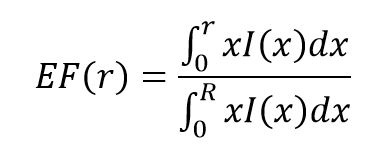
Where R is the integration limit (i.e. the radius of the fiber core).
EF(r) represents a fraction of cumulative near-field power to total output power as a function r. Different EF requirements are defined for 50 μm and 62.5 μm MMF at 850 nm and 1300 nm.
EF Compliance and MMF Cable Loss Measurements
Historically, OFL condition prevailed when numerical aperture or the beam diameter of an optical light source, such as a laser or LED, exceeds that of the fiber core.
Because new high-speed light sources (i.e. VCSELs) don’t have an OFL power distribution profile, it makes sense to adapt the fiber cable loss measurement method to the actual light source. In the latest IEC and TIA standards, the launch condition must meet the requirements of the specified encircled flux template for 50 μm MMF at 850 nm.
Why EF-Compliant Launch Conditions Matter
There are a few important reasons why EF-compliant launch conditions are important during testing:
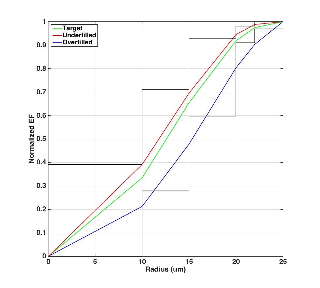
- An overfilled fiber will have less power near the core and more power in the outer region of the core, so it becomes the lower curve (in blue above). This leads to a slightly pessimistic insertion loss (IL) readings (higher than the actual IL) on the test cable assemblies with false link failures.
- An EF-compliant launch condition specifies a power distribution region along the core radius (in green above). It simulates the VCSEL power distribution profile that leads to more accurate insertion loss readings, and provides significant improvements in measurement repeatability.
- The target EFL condition of the light source is set to represent the worst-case scenario for high-speed links, such as 40G and 100G Ethernet; therefore, the measurements performed with an EF-compliant launch will provide a repeatable, conservative measurement of link attenuation for such applications.
- EFL conditions can considerably improve the consistency of field measurement by reducing cable loss measurement uncertainty from greater than 40% to less than 10% on a dB basis.
- An underfilled launch will have more power near the center of the core and less power in the outer regions of the core, so it becomes the upper curve (in red above). This will lead to a slightly optimistic IL reading (lower than the actual IL) that could lead to potential network link failures.
As the evolution of active and passive optical components (and optical fiber itself) continues to improve, we’ll keep you updated here. Belden’s multimode fiber solutions optimize fiber for increased bandwidth by using multiple wavelengths in the lower end of the spectrum. Learn moreabout the experience and expertise we can bring to reduce costs, improve uptime, make the best use of space and ensure security.
About the Author
![System.String[]](https://assets.belden.com/transform/d88d257f-c23d-4a61-b354-d49d9932ec65/qing-xu?io=transform:fill,width:300,height:300)
With 13 years of experience in optical communications and photonics device design, Qing Xu is a subject-matter expert in not only optical fiber technology, but also signal transmission, data center trends, fiber/copper connectivity and structured cabling. During his time with Belden, he closely monitored and participated in industry activities related to optical fiber communications systems, data center technology and trends.