Follow IEC 60603-7 to Ensure Reliable Cable Connections
When it comes to our networks, we pay a lot of attention to the cable we select – and that, of course, makes sense. After all, cable is responsible for moving our valuable information from one place to another. But to truly complete that data-transmission path – and get the data where it needs to go – connectors like plugs and jacks are just as important.
I once was told, “The worst thing you can do to a cable is put a connector on it.” I was quite angered by that comment. All of the effort and thought that goes into making the best connector were shot down in that one statement. But, it’s true. The best, most robust cable in the world won’t perform correctly if its connectors aren’t designed properly – especially if they do not fit together properly.
Some connector problems – especially those involving intermateability – can be prevented by following IEC 60603-7 specifications.
What is IEC 60603-7?
IEC 60603-7 specifications cover the common dimensions, mechanical, electrical and environmental characteristics (and applicable tests) for plugs and jacks.
By defining the performance factors for these RJ45 connectors, IEC 60603-7 allows plugs and jacks from any vendor to be successfully mated.
Not only does IEC 60603-7 cover physical dimensions of plugs and jacks, but it also references high-frequency performance requirements for shielded and unshielded RJ45 connectors. These specifications ensure that all plugs and jacks compliant with this standard will be intermateable.
Why is IEC 60603-7 Important?
In some cases, if IEC 60603-7 standards aren’t followed, plugs and jacks can’t mate correctly. For example, I once attempted to connect a plug into a simple tabletop router jack. Because of the way the router’s jack was designed, there wasn’t enough clearance to accept the plug I was using – the jack wasn’t IEC 60603-7 compliant. This prevented the patch cord plug from being completely inserted into the proper electrical contact point.
Electrical Contact Points
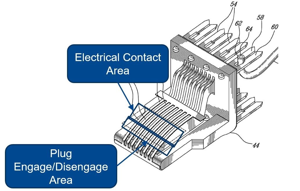
IEC 60603-7 also provides guidance on where contact should be made once a plug and jack are connected. According to the standard, the electrical contact should be made on the radius of the piercing insulation contact (PIC) – not on the top of the PIC. (See the image below.)

The electrical contact point on the radius of the PIC allows the plug to disengage outside the contact area, and ensures that plug removal won’t harm the data signal path in any way.
IEC PoE Reliability Testing
When it comes to plug removal under Power over Ethernet (PoE) load, there is currently no standard to meet. Instead, IEC 60512-99-001 offers a test method, or testing guidance. In a successful test, after 100 cycles at 600mA, the contact resistance change must be < 20 mΩ.
An updated version of this standard – IEC 60512-99-002 – is currently in draft form. Initially, it called for < 20 mΩ contact resistance change after 100 cycles at 1000mA. Now, it will call for < 20 mΩ contact resistance change after 100 cycles at 2000mA.
Belden’s connectivity solutions are always designed to meet all IEC electrical, mechanical and reliability requirements to ensure that plugs and jacks will successfully connect. Learn more about our newest connectivity system – REVConnect – here.
About the Author
![System.String[]](https://assets.belden.com/transform/0994b259-c761-40ea-9128-f942c2913e9f/ron-tellas?io=transform:fill,width:300,height:300)
Ron joined Belden in 2016 to help define the roadmap of technology and applications in enterprise. Prior to this, he developed cables and connectivity for Panduit and Andrew Corp. Ron Tellas is a subject-matter expert in RF design and Electromagnetic Propagation. As a Technology and Applications Manager, Ron focuses on Local Area Networking. He represents Belden in the ISO WG3 committee, TIA TR42 Premises Cabling Standards, IEEE 802.3 Ethernet Working Group and served as a committee member of NFPA 70 Code-Making Panel 3. Ron is the inventor of 16 US patents. He has a Bachelor of Science degree in Electrical Engineering from Purdue University, a Master of Science degree in Electrical Engineering from Illinois Institute of Technology, and a Master of Business Administration from Purdue University.