
So what will the new fiber requirements be as you move toward 100G Ethernet speeds? And how do you get structured cabling ready for upgrades to 200G and 400G in the future?
Because multimode fiber (MMF) is the most popular structured cabling system used in data centers (except for hyperscale data centers), we will focus on MMF cabling in this blog. Singlemode fiber (SMF) deployed in hyperscale cloud data centers employs application-optimized topology, but the connectivity solution is similar to MMF.
Duplex Fiber Cabling Installation
Edge pluggable 10G SFP+ (small form factor) is the de facto single-lane transceiver used not only in datacom applications, but also in telecom applications, for its versatility and high density.
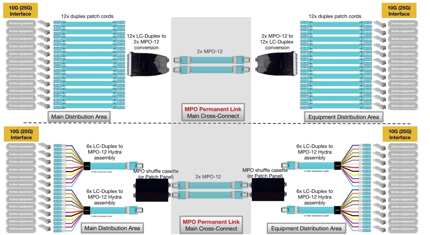
In data center environments, servers equipped with 25G ports use the SFP28 form factor (the same as SFP+ but at 2.5 times the speed) with the same LC Duplex optical fiber connector interface. In fiber-rich data center environments, arrayed connectors (MPO-12, MPO-24, etc.) and trunk fiber cables are usually installed as main cross-connect (horizontal link) fiber cables:
- An LC Duplex-to-MPO conversion cassette is used at the main distribution area (MDA) where the servers are located; another conversion cassette is used at the equipment distribution area (EDA) to redistribute optical links to the switch ports with LC Duplex.
- A hydra cable assembly (breakout fiber cable) can be used instead of cassettes to connect to the main cross-connect MPO fiber trunk via a patch panel. An optical shuffle cassette supports CLOS networks in spine-leaf data center architecture.
Parallel Fiber Cabling Installation
The most popular form factor for switch ports has become 40G QSFP+ (and 100G QSFP28). QSFP (quad small form-factor pluggable) is a four-lane duplex hot pluggable mainly designed for datacom applications. 40G QSFP+ (or 100G QSFP28) has a 2.5x edge density compared to SFP+ (or 25G SFP28), and uses four parallel 10G (or 25G) lanes.
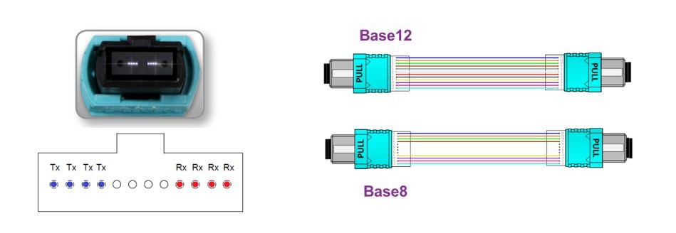
The optical interface is a receptacle for the MPO female connector. Four fibers (1, 2, 3 and 4) are used for transmitting; the other four fibers (9, 10, 11 and 12) receive the optical signal.
Although other form factors exist, such as the 100G CXP with 10x 10G lanes, the QSFP solution offers the best option in terms of interoperability, thermal management and cabling costs. QSFP transceivers, paired with low-cost parallel fiber connectivity with one row of MPO-12 or MPO-8 connectors, serve as flexible breakout or trunk cabling connections.
Today, over 95% of 40G transceivers sold and installed are QSFP+ modules:
- 40G/100G direct links are typically used in switch-to-switch links.
- 40G/100G Ethernet ports can be configured as 4x 10G or 4x 25G ports to support 10G/25G server links.
- 40G/100GBASE-SR4 transceivers only use eight fiber threads in an MPO-12 connector; therefore, a Base-8 solution is a cost-optimized cabling solution that allows 100% fiber utilization.
When migrating from 10G cabling infrastructure to a parallel fiber cabling infrastructure, MPO permanent links can be reused with optimization.
When used for 40G or 100G switch-to-switch direct links, an MPO-12-(Base-8)-to-MPO-12-(Base-12) conversion can allow 100% fiber reutilization of the installed horizontal cabling. In this example below, 3x MPO-12 (Base-8) cable assemblies are converted into two MPO-12 (Base-12) connectors.
When connecting to 10G or 25G server ports, MPO-12-to-LC Duplex hydra cable assemblies support breakout configuration to 40G or 100G server ports. In addition, shuffle cassettes can allow flexible CLOS network spine-leaf architecture when necessary.
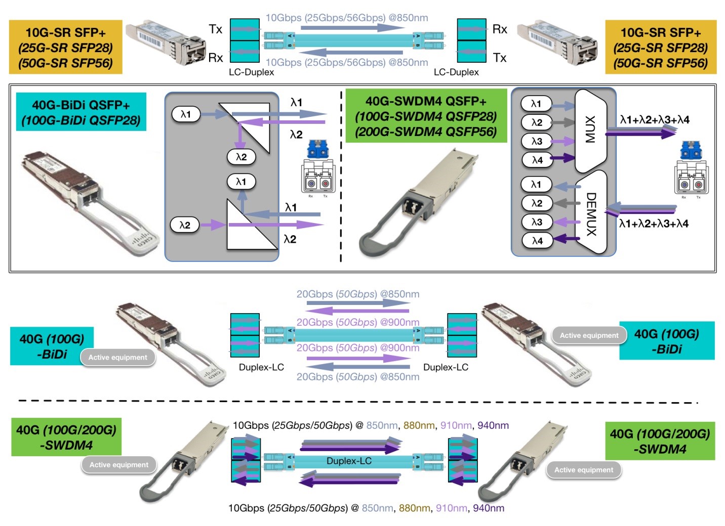
Enabling Higher Bandwidth with Wavelength Division Multiplexing
In a breakout configuration from switch to server, a parallel fiber solution like 40GBASE-SR4 or 100GBASE-SR4 is ideal because it optimizes switch faceplate density and fiber cable management.
For direct connection, it’s more desirable to use duplex fiber pairs for cost savings. Wavelength division multiplexing (WDM) has been widely used in telecom applications to save singlemode fiber counts. Recently, WDM technology has also been adopted in multimode optics to simplify fiber cable management; lower fiber counts and connectivity costs allow for the reuse of installed duplex fiber pair for smooth speed upgrades.
New alternative transceiver modules like 40G/100G-BiDi and 40G/100G-SWDM4 are already available to the market, allowing the use of LC Duplex instead of MPO-12 to reduce fiber count by a factor of four.
The Importance of High-Quality Fiber Connectivity
In some cases, installed legacy fiber cables can be reused (as we have illustrated in this blog); however, the risks must be understood. Performance of some legacy fiber cable may no longer meet minimum link requirements in a new system.
To futureproof your data center fiber infrastructure, read some of our other blogs and refer to the latest industry standards and installation guidelines.
At the End of the Road to 800G
This blog marks the last in our series covering the road to 800G Ethernet. As part of this blog series, we’ve also covered the following topics:
- The road to 800G Ethernet
- New pluggable form factors
- The evolution of high-speed interfaces and Ethernet switches
- Layer 0 copper connectivity
- Layer 0 fiber connectivity
- 40G vs. 100G
Our copper and fiber cabling and connectivity solutions are designed to help you prepare for 800G Ethernet speeds. Are you ready? Learn more here.
About the author
Qing Xu
Technology and Application Manager, Optical Fiber Systems
With 13 years of experience in optical communications and photonics device design, Qing Xu is a subject-matter expert in not only optical fiber technology, but also signal transmission, data center trends, fiber/copper connectivity and structured cabling. During his time with Belden, he closely monitored and participated in industry activities related to optical fiber communications systems, data center technology and trends.