
Because fiber systems are directional, maintaining polarity is crucial. It defines the direction that optical signals travel inside the fiber. Without polarity, data won’t flow the way it needs to.
Ensuring proper polarity means that “transmit” talks to “receive.” In other words, the transmit signal (Tx) at one end of the channel needs to match the corresponding receiver (Rx) at the other end.
Many factors impact fiber polarity—and they all have to do with how fiber components interact with one another:
- General fiber polarity (straight, flipped, crossed, etc.)
- Pinning (pinned/unpinned), often referred to as gender (male/female)
- Orientation
- End-face alignment
- Pinning
- Etc.
The 3 common types of fiber polarity
In ANSI/TIA-568.3, Optical Fiber Cabling and Components Standard, TIA defines Types of fiber polarity components to be used in Methods of polarity, including:
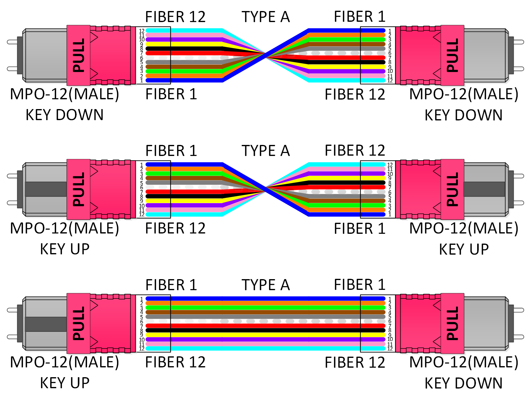
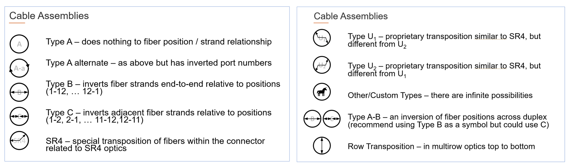
- Type A (straight-through): The fiber at position 1 on one side is the fiber at position 1 on the other side.
- Type B (inverted): A longitudinal “flip,” where the fiber at position 1 on one side is at the final fiber position (position 12) on the other side.
- Type C (twisted-pair): A pair-wise “flip,” where each fiber pair is flipped from one side to the next. For example, the fiber at position 1 on one end arrives at position 2 on the opposing end, while the fiber at position 2 is the fiber at position 1 on the other side.
Stop drawing fiber polarity—and start mapping it instead
It’s not uncommon for engineers, designers and installers to use graphics software to “draw” fiber polarity for optical fiber cabling systems. Below is an example of what these drawings look like.
Click the images to expand.
These three sketches all represent Type A fiber polarity. Upon first glance, they look different—but they’re actually all the same. The only differentiating factor is the perspective from which the connectors are shown.
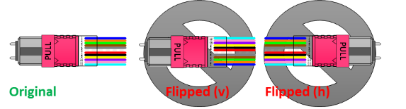
While drawing tools may make it simple to draw fiber polarity, they also make it too easy to accidentally manipulate drawings incorrectly leading to an error in polarity planning. For example, a vertical flip changes orientation. A horizontal flip changes fiber position numbering. These mistakes make it difficult to reuse drawings or rely on them to make changes.
That’s why we’re working closely with TIA to change the way the industry draws or maps fiber polarity. While TIA-TSB-5069, Optical Fiber Channel Polarity, aids in mapping and planning, there’s room for improvement.
The goal: to shift the industry toward using visual symbols—very specific types of symbols—instead of drawings. Why? Because symbols convey lots of information in a single glance. (Think about no-smoking signs or pedestrian-crossing signs, for example.) They bring order to how the industry describes, visualizes and models fiber polarity.
Within these symbols, we can capture and represent each component’s impact on overall system polarity, including:
- Connector keyway alignment/orientation, such as mating compatibility, pinning and multi-row optics
- Fiber position in the connector
- Strand identifier, such as color
- Port positioning in frames, modules and cassettes
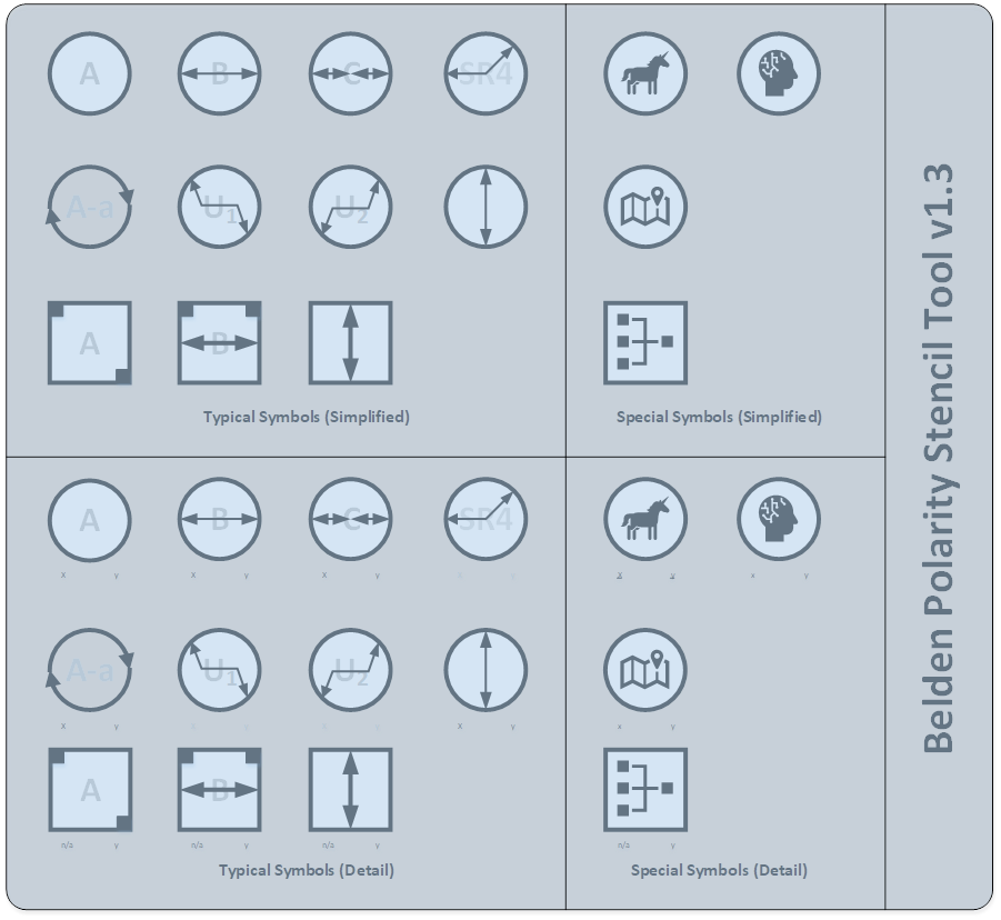
One change we’re suggesting is the shape of symbols. In TIA-TSB-5069, only round symbols are used. The symbols aren’t intuitive or easy to understand, especially when mapping a complex fiber channel. For example, when symbols are all one shape, you can’t keep track of or differentiate between cables and adapters.
For this reason, adapter symbols will be square in shape, while the symbols for cable assemblies will remain round. Inside the shape will be visual information that represents what’s happening inside that cable or adapter.
An empty square or circle indicates nothing unusual with the fibers—everything is as you would expect: one goes to one and so on. Directional arrows or squares displayed inside the shapes visually represent what’s happening with the fiber relative to their position in the fiber connectors.

Click the images to expand.
Benefits of fiber polarity mapping
Using symbols vs. drawings for fiber polarity mapping offers many benefits:
- As they expand (Base-2, Base-8, Base-12, Base-16, etc.), they’re independent of color and color codes
- They aren’t susceptible to the potential corruption possible with drawing tools
- They’re easy to use for a quick gut-check on configuration layout and design
- Typical fields can be added to the symbols to represent attributes like strand count, pinning, length, loss profile etc.
- They add depth to the design by allowing specific fields to be used for part numbers, purpose, etc.
- They create a common framework that makes documentation and training easier
If you want to learn more about mapping fiber polarity using symbols, and what this means for you, watch our Polarity Mapping Basics webinar. Two of our fiber experts carefully explain these upcoming changes, walk you through the new symbols and describe in detail what these changes mean for you and your fiber projects.
Click the image to expand.
Related resources:
About the author
Henry Franc
Field Applications Engineer
With an emphasis on data center design, planning and building, Henry Franc acts as a trusted advisor for large or complex projects across all verticals assessing clients’ business needs and finding the best technology options to meet them. He was also elected by industry colleagues to serve as vice-chair of the TR42 Telecommunications Cabling Systems Engineering Committee.