
Category 3 through Category 8 cabling, both UTP and shielded, contains four twisted pairs of insulated copper conductors. Each solid colored conductor is paired with a “white” conductor, which is a striped combination of white and the solid color.
For standards-based category cabling, these conductors are terminated on the ends of male (plugs) and female RJ45 connectors (jacks).
RJ45 Plug Termination
Patch cords are used to connect devices, such as PCs to switches. Often, plugs are sold as factory-terminated patch cords, but it’s not uncommon to make patch cords in the field.
Two wiring standards exist: T568A and T568B. The major difference between the two: the pin positions for the green and orange pairs are switched.
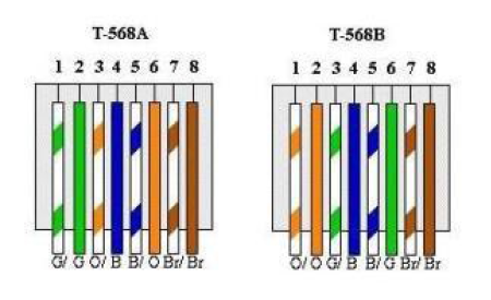
Using one versus the other is often dictated simply by history and inertia: T568B is frequently used in North America due to AT&T’s old 258A color code. While new construction projects can be cabled following either T568A or T568B, it’s imperative to stay consistent so that wires colors and stripes match up when plugs and jacks are connected. Otherwise, data signals won’t transfer.
For conventional 10-Mbit/s and 100-Mbit/s Ethernet, only pins 1, 2, 3 and 6 are used for signal transmission. All four pairs are used for 1000BASE-T and above.
10BASE-T and 100BASE-T node devices with uplink ports, such as PCs and routers, transmit data on pins 1 and 2, and receive on pins 3 and 6. Hubs and switches, on the other hand, transmit information on pins 3 and 6 while receiving on pins 1 and 2.
It makes sense to terminate patch cords that are straight-through pin out (T568A to T568A or T568B to T568B) when connecting these devices. Only in rare cases, such as PC-to-PC connections, should one end be terminated T568A with the other T568B. These patch cords are often called crossover cables.
Many modern devices can automatically detect connections and introduce a crossover signal transmission if required.
RJ45 Jack Termination
The color coding of jacks depends on the wiring inside the module. Jacks often contain leadframes (a continuous piece of metal) or PCBs (printed circuit boards) that route the signal from the cable/back of the jack to the pins.
When terminating a jack, follow the color code printed on the housing for T568A or T568B. As you can see in the image displaying a variety of jacks, the jack color coding varies; be sure to read the label carefully.
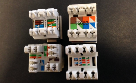
Different manufacturers – and even different connectors from the same manufacturer – could have different color codes.
At Belden, we’re always searching for ways to make cabling installation an easy, straightforward process – including the use of easy-to-follow color codes. For more termination tips and techniques, please visit our Installations Guides or contact us at 800.BELDEN.1.
About the author
Kristen Poulos
Vice President/General Manager of Belden Industrial Cyber Security
Kristen is the Vice President/General Manager of Belden Industrial Cyber Security. She has previously held the role of Vice President of Marketing for the Enterprise Platform and before that worked within the product line management team and Mohawk brand. She started with Belden as a summer intern in 2010 and joined full time in 2011. In her spare time, she enjoys outdoor activities with family and two Australian Shepherds.