Sufficient Power Budget is Key to Future Proofing Fiber Infrastructure
With the technology changes happening in today’s enterprises, all types of organizations – from hotels and gaming facilities to schools and offices – are deploying new fiber cabling infrastructure.
Before you make the leap, however, it’s important to understand the power budget of the new architecture, as well as the desired number of connections in each link. The power budget indicates the amount of loss that a link (from the transmitter to the receiver) can tolerate while maintaining an acceptable level of operation.
For this reason, this blog provides you with multimode fiber (MMF) link specifications so you can ensure your fiber connections have sufficient power for best performance. In an upcoming blog, we’ll cover the link specifications for singlemode fiber.
Attenuation and Effective Modal Bandwidth
The latest IEC and ANSI/TIA standards ratified the maximum cabled fiber attenuation coefficients for OM3 and OM4 to 3.0 dB/km for cabled fiber at 850 nm. Attenuation is also known as “transmission loss,” and is the loss of optical power due to absorption, scattering, bending, etc. as light travels through the fiber. OM4 can support a longer reach than OM3, mainly due to its better light-confining characteristics, defined by its effective modal bandwidth (EMB).
OM5 is backward compatible with OM4 at 850 nm, but can support shortwave wavelength-division-multiplexing (SWDM) between 840 nm and 953 nm.
VCSEL Spectral Width
VCSEL spectral width is an important factor in fiber chromatic dispersion. (Chromatic dispersion is the act of the on-off light pulses that convey digital information “spreading out.”) Typically, larger laser spectral width (ΔλC) causes a higher chromatic dispersion penalty, leading to an increase in signal-quality degradation.
As 10 Gbps VCSELs have become commercialized, spectral width has been relaxed to allow large-scale, low-cost production without wafer-safe individual testing. Initially, 10GBASE-SR transceiver reach targets for OM3 and OM4 were 300 m and 550 m. The reach limit for 10GBASE-SR in OM4 was ratified to 400 m in IEEE 802.3.
To compare, 10GBASE-SR, 40GBASE-SR4 and 100GBASE-SR10 use 10 Gbps VCSELs as the transmitter laser source for one-lane, four-lane and 10-lane transceiver solutions; however, the root-mean-square (RMS) spectral width for 10 Gbps VCSEL in the 10GBASE-SR standard and 40GBASE-SR4/100GBASE-SR10 standard are defined differently (0.45 nm for 10GBASE-SR and 0.65 nm for 40GBASE-SR4/100GBASER-SR10).
The relaxed spectral width specification in IEEE 802.3ba for 40GBASER-SR4 and 100GBASE-SR10 transceivers further reduces the operating distance to 100 m (OM3) and 150 m (OM4).
Ethernet Link Model
In IEEE 802.3bm, the 25 Gbps VCSEL RMS spectral width for 100GBASE-SR4 is again reduced to 0.6 nm; however, due to the data speed increase of 2.5, even when using forward error correction (FEC) to relax the raw bit error rate (BER) target to 5×10⁻⁵, the operating distance has to be reduced to 70 m (OM3) and 100 m (OM4).
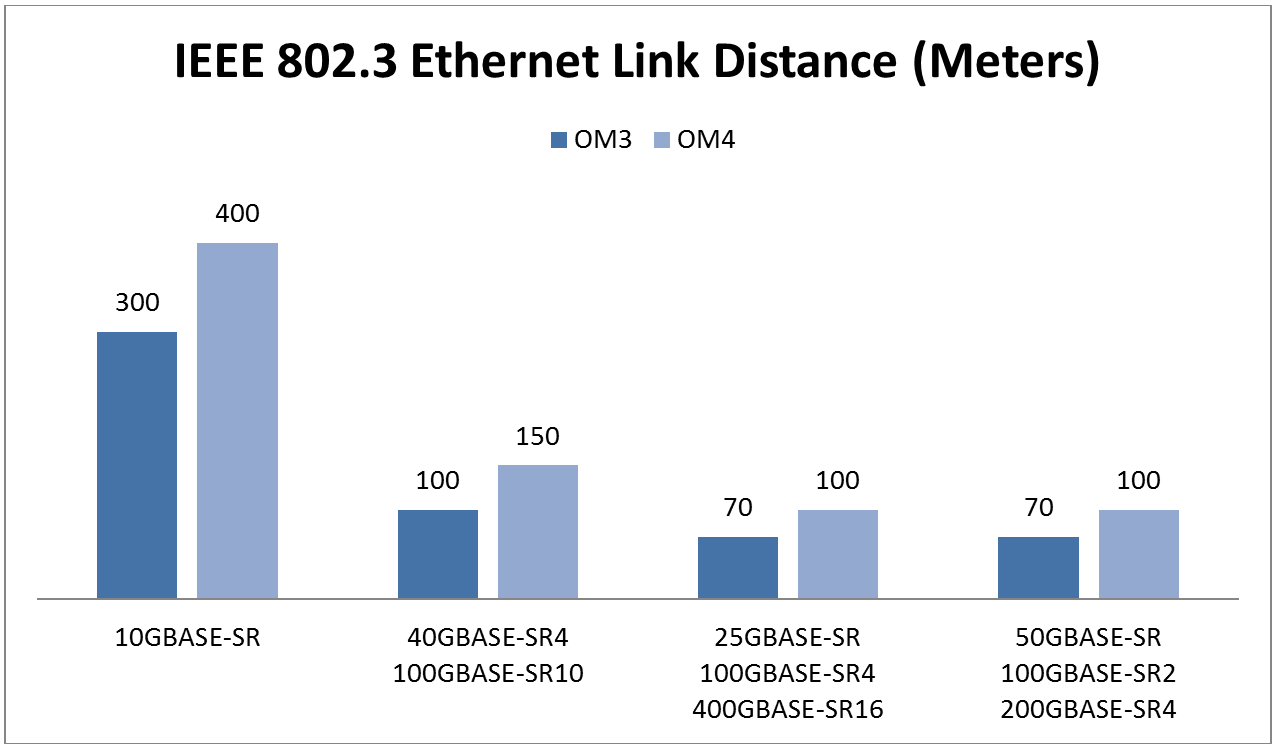
IEEE 802.3 Ethernet link distance for different speeds
In the Ethernet multimode fiber link model, channel insertion loss includes fiber cable loss plus 1.5 dB allocated for connection and splice loss at 850 nm, except for 40GBASE-SR4 and 100GBASE-SR10, which allocate only 1.0 dB for connection and splice loss.
The loss of a single connection shall not exceed 0.75 dB. The initial connection to the physical medium dependent (PMD) sublayer at the medium dependent interface (MDI), as shown below, is not considered part of the channel link loss.
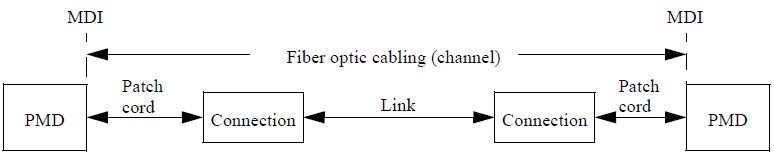
IEEE 802.3 Ethernet transceiver link model
It’s important to note that channel insertion loss is considered part of the transceiver power budget. These two terms are not interchangeable. For example, although the power budget of 40GBASE-SR4 is ~1 dB higher than that of the 10GBASE-SR, the channel insertion loss budget is considerably reduced due to other penalties.
The allocation for penalty includes jitters, inter-symbol-interference (ISI), laser intensity noise, reflection, chromatic and modal dispersion. When comparing an ideal transmitter with a very short fiber against the transmitter under test with rated fiber dispersion, this is the difference in sensitivity for a reference receiver.
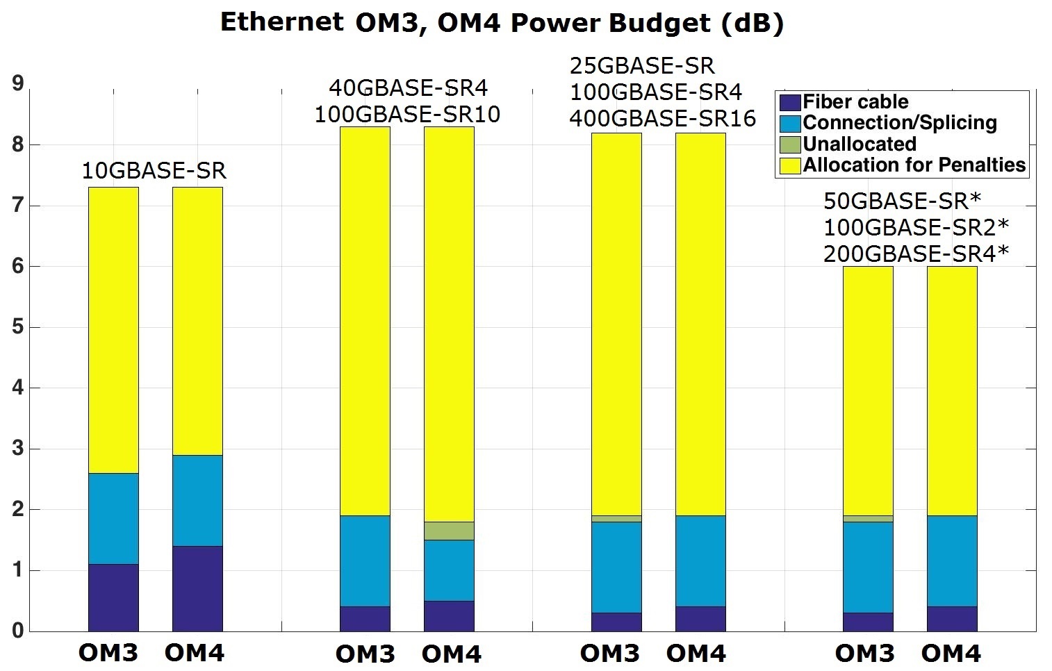
IEEE 802.3 Ethernet MMF link power budget, *in progress
When moving from single-lane (10GBASE-SR) to parallel-lane (40GBASE-SR4) systems, it becomes increasingly difficult to achieve good signal integrity due to additional noise and relaxed VCSEL spectral width.
The link power budget allocated for channel insertion loss is reduced from 2.6 dB/2.9 dB (10GBASE-SR) to 1.9 dB/1.5 dB (40GBASE-SR4) for OM3/OM4, while allocation for penalties have increased from 4.7 dB/4.4 dB to 6.4 dB/6.5 dB for OM3/OM4.
Moving from 10G per lane to 25G per lane is even more challenging; the clock-data-recovery (CDR) integrated circuit (IC) has been added to the building block that helps regenerate the clock and data. In IEEE 802.3, Clauses 91 and 108, Reed-Solomon forward error correction (RS-FEC) has been implemented for 100GBASE-R PHYs and 25GBASE-R PHYs.
In IEEE 802.3bm and 802.3by, 100GBASE-SR4 and 25GBASE-SR use RS-FEC (528, 514) to relax the raw BER to 5×10⁻⁵ at the PMD to provide a BER better than 10-12 at the MAC/PLC service interface.
The transmitter and dispersion penalty (TDP) metric is used for 40GBASE-SR4 and 100GBASE-SR10 models; the transmitter and dispersion eye closure (TDEC) metric is used for 25GBASE-SR, 100GBASE-SR4 and 400GBASE-SR16 models.
For next-generation 50GBASE-SR and 200GBASE-SR4, the PAM4 modulation format has been adopted by the IEEE 802.3bs and 802.3cd taskforces. There will be an additional power penalty on optical signal-noise-ratio (SNR) of 4.8 dB, and the TDECQ (TDEC for PAM4) will be used as the penalty metric instead of TDEC.
Although using the PAM4 modulation helps leverage 25G photonics components for 50G data transmission, it also comes at the cost of reduced total link budget to maintain MMF operating distance.
Fibre Channel Link Model
In Fibre Channel standards, although the bit rates are different from Ethernet, the maximum link distance also decreases at higher speeds.
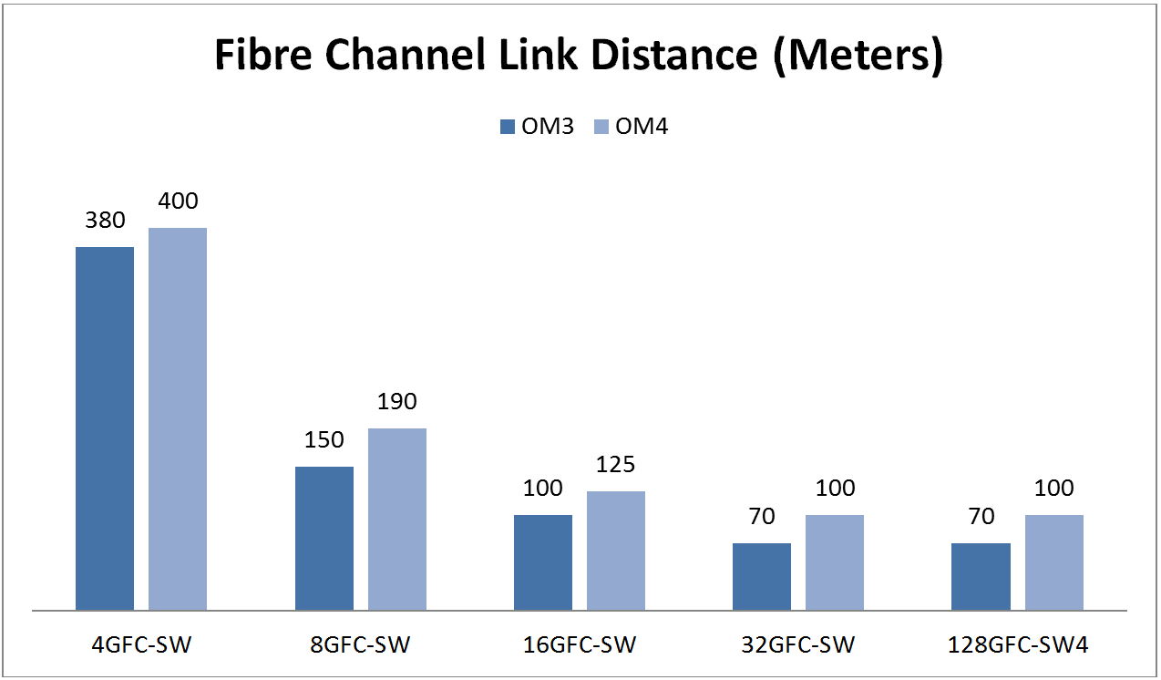
Fibre Channel link distance for different speeds
Similar to the Ethernet standard, Fibre Channel MMF links are standardized with 1.5 dB of total connector loss, except for 128GFC-SW4, which specifies a total connector loss of 1.0 dB. Just as the Fibre Channel signaling rates differ from those of the Ethernet, so do the link distance limits and link budgets.
The same link model also applies to the Fibre Channel link model. The ISI penalty, as a function of the fiber’s bandwidth, contributes to a large portion of the optical penalties; therefore, it is specified separately in the Fibre Channel standard.
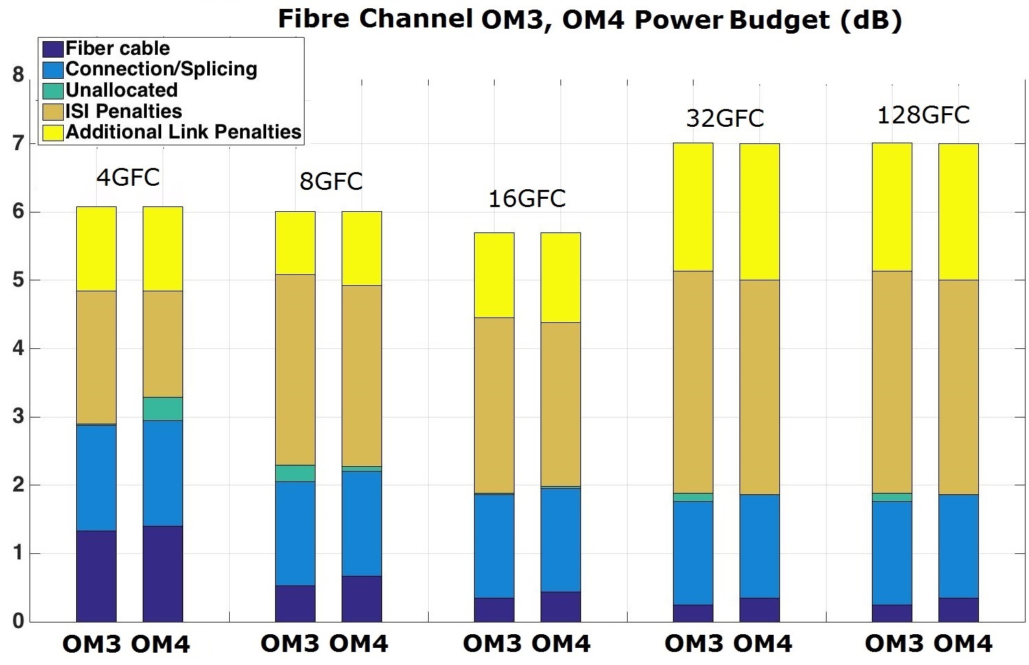
Fibre Channel MMF link power budget
As data rates increase, Fibre Channel will also encounter more signal impairments and reduced reach, similar to the Ethernet standard.
Comparing the 128GFC (signaling rate of 28.05 Gbps) to Ethernet 100GBASE-SR4 (signaling rate of 25.78125 Gbps) with the same reach specification (70 m in OM3 and 100 m in OM4), the power budget of 128GFC is 0.4 dB lower (7.8 dB vs. 8.2 dB), and the channel insertion loss of 128GFC is 0.54 dB lower (1.36 dB vs. 1.9 dB).
As chromatic dispersion and modal dispersion penalties become more severe with longer MMF links, link distance is another factor that induces signal quality degradation in MMF transmission; it typically gets worse with longer-distance links.
In the Fibre Channel MMF link specification, the allowed channel insertion loss budget changes as a function of distance and total connector loss. We highlight the standard specifications at the maximum supported length in which the total connector loss is specified as 1.5 dB – except for 128GFC-SW4, where total connector loss is specified as 1.0 dB to obtain a reach of 70 m (OM3) and 100 m (OM4) fiber.
In the Fibre Channel standard, higher connector loss or longer distance is supported, but the supported link distance and channel insertion loss budget also depends on total connector loss. This allows end-users to use “engineered links” and make trade-offs between reach and total connector loss.
Belden fiber connectivity systems are faster, easier and better to use. Our data center cable and connectivity solutions reduce complexity, increase flexibility and streamline installation during new fiber projects. Learn more here.
Working with a high-quality, trusted data center partner can go a long way toward ensuring that you have a futureproof fiber system you can afford, and that supports your organization for years to come.
To learn more about partnering with Belden for your data center project, visit here.
About the Author

With 13 years of experience in optical communications and photonics device design, Qing Xu is a subject-matter expert in not only optical fiber technology, but also signal transmission, data center trends, fiber/copper connectivity and structured cabling. During his time with Belden, he closely monitored and participated in industry activities related to optical fiber communications systems, data center technology and trends.