Understanding Fiber Polarity at the Component Level, Part 1
Recently, we explored how to provide a fiber solution that achieves the correct polarity with absolute certainty – it was the first blog in a four-part series.
In a future blog, we’ll discuss what TIA has to say about polarity Methods, as well as how various Types of components interact with each other. (TIA has addressed the challenges associated with achieving the correct polarity, and continues with its work to make it easier to understand, plan and implement complex channels.)
Before we discuss that, however, let’s step back and make sure we cover the different Types of components and how they interact with polarity.
At first blush, the concepts and solutions can be confusing – mainly because of the highly complex way in which polarity schemes are illustrated. To make better sense of how these schemes (or Methods) work, we need to understand what each of these components (Types) does. It’s important to differentiate between Types of components and Methods of polarity.
Methods are made up of many component Types. Unfortunately, standards language uses similar labels: A, B, C, etc. So, a Method (X) will be made up of numerous component Types (X, Y, Z, etc.). This language must remain consistent – not just within standards, but also within applications, or things will become confusing.
When reviewing polarity Methods, there are differences between the ways to connect, different components and their Types.
There are multiple ways to connect devices using fiber optics:
- Simplex: A single fiber is used (uni- or bi-directional within the fiber) to plug things in in a one-to-one relationship. Let’s call this Base-1. Because Base-1 networks are the exception rather than the norm, we’ll wait until later to talk about how to address them to avoid confusion.
- Duplex: Two fibers are used. Let’s call this Base-2.
- Parallel: More than two fibers are used. Most often, we see parallel fiber optics with eight or 12 fibers in a single-row MPO connector. These would be called Base-8 or Base-12. There are also MPO connectors with more than 12 fibers in a single row (Base-16, for example), as well as multi-row MPO connectors with 24 or 32 fibers in dual-row formats (Base-24 and Base-32).
Two component Types are used in fiber systems: cable assemblies and couplers. When it comes to component Types, there are three basic configurations defined by standards, but there are others that are needs-dependent as well:
- Type A: A straight-through component where fiber position 1 on one side is fiber position 1 is on the other side.
- Type B: A longitudinal “flip” or cross where the first fiber position on one side is the last fiber position on the other side. In a duplex Base-2 example, it’s fairly simple: 1-2, 2-1. In a parallel Base-12 example, however, it gets a little more confusing: 1-12, 12-1, 2-11, 11-2, etc.
- Type C: A pair-wise “flip” where each fiber pair is flipped from one side to the next. In a parallel Base-12 example, it would go 1-2, 2-1, 12-11, 11-12, and so on. In a duplex Base-2 example, as you can imagine, it would work just like a Type B – because that’s a consequence of a duplex environment (and only in a duplex environment). We will continue to call them Type B just to avoid confusion.
- Needs-Dependent Lane Assignment: This is not currently defined by TIA, but an example would be SR4 lane assignment used by equipment vendors for things like 40GBASE-SR4. In this configuration (and it only applies to parallel optics), each transmit/receive lane is assigned to specific fiber positions within an MPO.
- Needs-Dependent “Other”: There may be special-use cases that require a specific fiber configuration. A rare, though practical, example would be a concatenated link using multi-row parallel optics. You need a special Type of component to ensure that your row and fiber positions are where you need them to be. They tend to be purpose-designed channels, and are not typically included in the majority of structured cabling needs.
In case this wasn’t confusing enough, let’s include some tertiary concerns that need to be addressed – gender, alignment and key positioning – before we move on to component interactions. These relate specifically to connectors and their interfaces.
Connectors and Interfaces: Gender
Gender is male, female or genderless (in the case of MPO couplers).
- Simplex connectors (LC, SC, etc.) are always male. They may be arranged as duplex in the case of LC Duplex (LCD) or SC Duplex (SCD), but they are, in practicality, just simplex connectors joined together by a clip or housing.
- Parallel optic connectors can be male or female. They look the same except for small alignment pins, which allow you to mate male-to-female.
- Simplex/duplex couplers are female, which allow male connectors to be plugged in on either end.
- Parallel optic couplers are essentially genderless and accept an MPO of any gender in either end. It’s critical to ensure the correct connector choice or you may damage one or both of the connectors and/or equipment.
Connectors and Interfaces: Alignment
Alignment is expressed in relation to the position of the key or latch. Connectors only have a key or latch that is used for alignment; however, couplers can have two fundamental configurations:
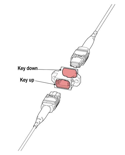
- Key Up to Key Up (KU/KU). KU/KU couplers are Type B devices. As you can see in the diagrams, both alignment keys are facing up. This provides a longitudinal flip, and keeps everything on the same vertical plane.

- Key Up to Key Down (KU/KD). KU/KD couplers are Type A devices. As you can see in the diagram, the keys are on opposing sides. This keeps the fiber positions the same in the longitudinal plane; however, in the vertical plane, it transposes them.
Connectors and Interfaces: Positioning
Positioning is for the placement of the key (latch) in relation to the body of the connector. In most instances, the position of the key is centered. MPO connectors are essentially of two designs 12 fiber rows (accommodates Base-8, Base-12 and and Base-24) and 16 fiber rows (Base-16 and Base-32). The traditional 12-fiber row MPO has a centered key (latch); the 16-fiber row MPO has an offset key (latch).
Now that we’ve reviewed the different component Types – let’s take some time to let that sink in! Next week, we’ll review how these component Types need to interact to provide a functional fiber system, as well as the operational considerations to make while reviewing Methods. Subscribe so you don’t miss this information!
About the Author

With an emphasis on data center design, planning and building, Henry Franc acts as a trusted advisor for large or complex projects across all verticals assessing clients’ business needs and finding the best technology options to meet them. He was also elected by industry colleagues to serve as vice-chair of the TR42 Telecommunications Cabling Systems Engineering Committee.