
Indoor Small Cell Overview
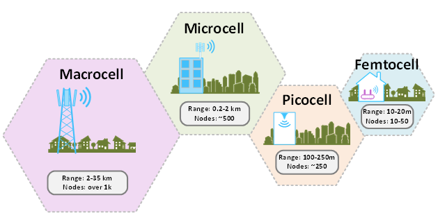
A cellular network is comprised of many macrocell sites that house electronic equipment and antennae to provide mobile device connectivity operating in the licensed spectrum. A macrocell can connect more than 1,000 devices over a large area (up to 35 km). There are many factors that determine the range and quantity of devices these macrocells can offer.
In areas with higher densification, or where coverage is impeded (such as by buildings, geographical landscape, etc.), smaller, lower-power cellular network nodes can be deployed to improve coverage and capacity. These cellular network nodes can be described as:
- Microcells, which provide 500 nodes over a 2 km radius
- Picocells, which provide 250 nodes over a 250 m radius
- Femtocells, which provide 10-50 nodes over a 20 m radius
A small cell can be any one of these smaller, lower-power cellular network nodes. This application guide focuses on indoor small cells, which are generally considered to be picocells or femtocells.
Download RF Design Files
Recommended Products
Belden small cell infrastructure products to enable coverage and capacity.


-
Evolution of Small Cell Technology
-
Demarcation Point
-
Distributed Unit
-
Radio Unit Small (Cell)
-
Considerations
-
Challenges
In 1991, the first global system for mobile communications (GSM) was deployed in Finland. This second generation of cellular networks provided a means for roaming between different carriers, improved coverage and introduced text messaging.
In 2001, Japan deployed the third generation of cellular networks, which standardized the network protocol to allow for international roaming. Other improvements via increases in speed and bandwidth further enhanced videoconferencing, streaming and voice over IP (VoIP) features. It was during this era that new devices, such as BlackBerry and iPhone, were introduced to fully connect individuals to the internet through the cellular network. It was also during this time that small cells were devised.
3GPP is the 3rd Generation Partnership Project, which unites several standard document organizations under one cellular network specification. In 2008, small cells were added to 3GPP Release 9 and used mainly as an offload technique.
In 2009, Sweden and Norway deployed long-term evolution (LTE). This fourth-generation cellular network greatly improved past-generation technologies to give us the high-quality video, streaming, coverage and global communications we enjoy today. Small cells are no longer just for offload, but also play a role in heterogeneous networks (HetNets). HetNets provide a seamless transition between different layers and different radio interfaces of the cellular network, thereby providing a consistent user experience on mobile devices.
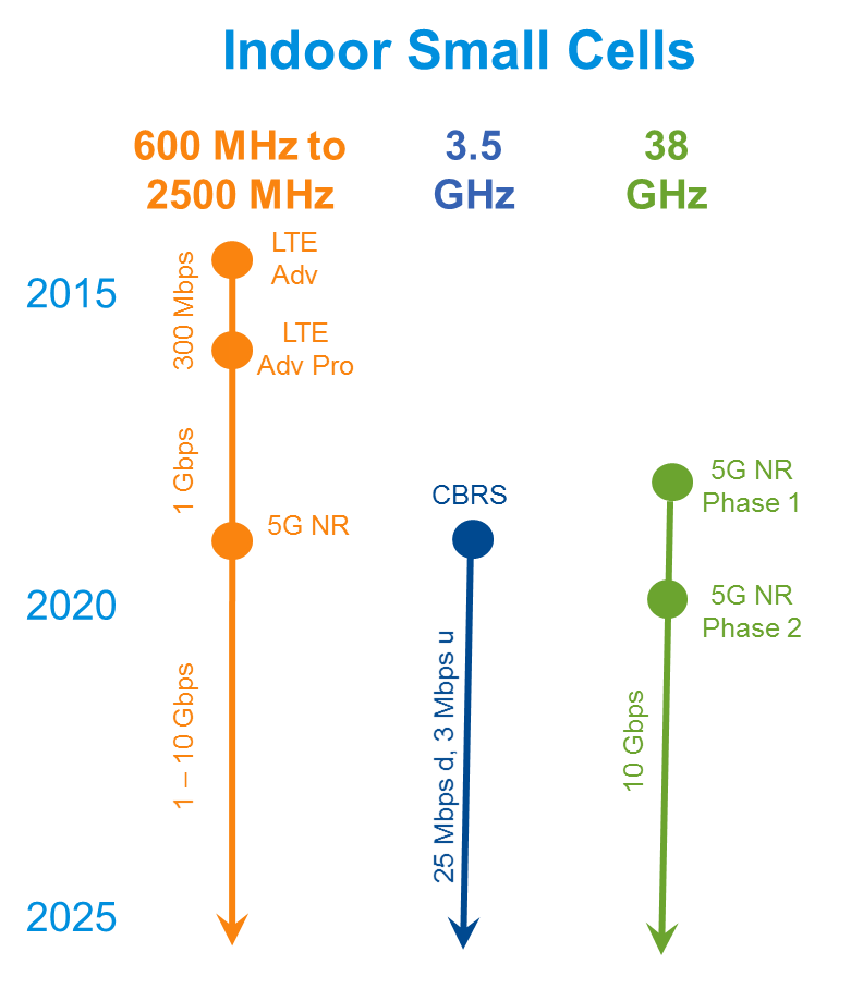
Today, cellular networks are evolving to support 5G. Unlike previous 'one-size-fits-all' upgrades, 5G offers a plethora of options, depending on the service required. 5G provides optimized support for a variety of services, traffic loads and end-user communities. It combines the latest in LTE technologies with 5G New Radio technologies to enable the objectives to support enhanced mobile broadband, massive machine type communications or ultra-reliable low latency communications. Depending on the application need, different levels of the set of objectives will be customized into customer networks. 5G is an EVOLUTION, not a REVOLUTION.
To provide the full advantages of 5G, new spectrum is being made available. The Citizens Broadband Radio Service (CBRS) in the 3.5 GHz band will increase wireless coverage—especially indoors. The abundant spectrum available in the 38 GHz mmwave bands will be capable of delivering extreme data speeds at close range to the antenna. Small cells will continue to be used for offload, HetNet and coverage to further promote the use of 5G technologies.
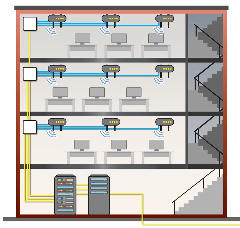
This is the physical point where the backhaul connection (S1 interface) from the wireless communications service provider enters the building. This is where operational control or ownership changes to the private network within the building.
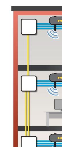
To support deployment of structured cabling in the ceiling, Zone Boxes can be used for grid cabling ceiling infrastructure. Grid cabling ceiling infrastructure consists of horizontal runs which are pulled to Zone Boxes. Within these Zone Boxes are panels with either populated REVConnect Jacks or Couplers.
Assemblies are deployed from these Zone Box panels to the wireless access points. Initial deployment can be made even faster using Pre-Terminated cables. Since moves, adds and changes (MACs) often occur for the changing needs within the Smart Building, only the assembly from the Zone Box to the new WAP location would need to be changed.
Grid cabling ceiling infrastructure can be supported through a traditional methodology whereas a work area outlet containing a jack is connected to the WAP with a patch cord. A newer methodology is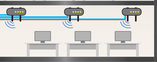 possible whereas the horizontal cabling (from the Zone Box or IDF) is terminated to a plug (or Flex-Plug) and directly connected to the WAP. Both methods are accepted by the standards and which one to use is entirely up to the system designer.
The cabling to connect data and power to the WAP in the Smart Building has moved to the ceiling. The air pace in the ceiling is typically an area that connects to the air space of the building. For this reason, we must be mindful of the cabling and components that connect to the WAP are plenum rated. For cabling, it must be CMP rated and for components, it must be UL 2043 rated.
To eliminate concerns about downtime, spotty connections or unreliable wireless service, how can you decide what type of cabling system foundation you need to support emerging wireless technology?
Consider the following:
Will this system support emerging wireless technology & wireless access points (specifically 802.11ac Wave 2 & Wi-Fi 6 devices)?
Next-generation wireless access points have Ethernet demands that exceed 1000BASE-T, requiring a Cat 6A system.
Will there be several MPTL endpoint connections?
End-to-end system reliability and simplicity are key to connecting devices to the network.
What will happen if your wireless goes down due to a cable or connectivity issue? Or if a network-connected security system fails?
Most wireless applications can afford very little, if any downtime and need cable and connectivity that ensure 24/7 reliability.
Is Power over Ethernet (PoE) involved in this application? (Will the system support power-hungry endpoint devices like security cameras, access control & building sensors?)
PoE relies on Cat 6A 4-pair, balanced, twisted-pair cabling for best performance due to its ability to reduce resistance and power waste.
RF Interference
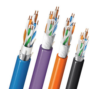
“Noise” is present in many environments, whether it’s an industrial plant (nearby machinery or equipment) or an office environment (fluorescent lighting, power cables, many cables in close proximity operating at different speeds, etc.) This noise can impact wireless cable and connectivity performance, data transmission and network traffic. Lower levels of category cabling are not designed to minimize this external noise (e.g., Cat 5e). Cat 6A cabling is the only cable designed to lessen external noise without employing mitigation techniques. It supports full implementation (100 m channels in high-density applications) of Multi-Gigabit Wi-Fi and Ethernet uplinks from 1G to 10G.

Belden’s REVConnect 10GXW System offers outstanding balance with superior TCL and ELTCTL levels, which translates to superior noise immunity that’s critical to optimizing in-building wireless network performance. In other words: Data signals will reach endpoint devices without reliability issues like slow speeds or downtime.
Power Delivery
Many wireless devices–especially IoT devices such as cameras and wireless access points–call for data transmission and efficient power delivery. Many of these devices must be placed where power isn’t easily accessible (i.e., ceilings, high on walls, plenum spaces).
Power over Ethernet (PoE) transmits data and power over a standard Ethernet cable. It’s a cabling technology that lets you deploy devices at any location–even far from electrical outlets. It also gives each connected device a dedicated IP address for individual management and control.
When comparing category cabling options for Wi-Fi applications, Cat 6A cable is the best option. It operates at frequencies of up to 500 MHz–twice that of Cat 6–and provides the most efficient power delivery to keep power waste to a minimum.
Heat Generation
Because power is transported over an Ethernet cable in most Wi-Fi applications, extra heat may be generated. When cables are bundled, heat can build up even more, negatively impacting cable performance. Some Category 6A cables have enough insertion loss margin to handle the extra heat generated from delivery of high power in tightly packed cables without impacting performance.
For example, Belden 10GXS Cable can handle the added heat while maintaining its full 100 m performance. It’s the only Category 6A cable that can make this claim. (Some cables quickly become an 85 m solution if the temperature increase is too high.)
Direct Connect (MPTL)
Many wireless and IoT devices are now being installed above the ceiling or on the wall for practicality and aesthetic purposes. This means that traditional network-connection methods need to change. A new topology known as “modular plug terminated link” (MPTL), or what we like to call “direct connect,” allows the horizontal cable to be terminated on one end to an RJ45 plug that connects directly to a device. This simplifies installation time and costs, promotes safety, creates a cleaner appearance and supports plenum applications.
Supporting the MPTL topology, the REVConnect Connectivity line uses a single termination process for every application. It offers a complete connectivity solution for Cat 5e, 6 and 6A shielded and unshielded cable, allowing you to switch from a jack to a plug–or vice versa–without having to re-terminate.
Plenum-Rated Connectivity
Because many of these devices connect above the ceiling, the outlets, jacks and patch cords used in these applications must now be plenum rated. Belden’s REVConnect Connectivity Systems are UL 2043 rated for plenum spaces for peace-of-mind that you’re using safe connectivity, regardless of device location.